
Simple dimmable light with ESPHome

In this entry, I will provide a general walkthrough on how to build a dimmable LED light, controlled with ESPHome and Home Assistant, and also including a physical control knob.
This post will not be a comprehensive set of instructions on how to use ESPHome or how to build PCB. But even if you are not familiar with those two topics, you may find some takeaway ideas in this post. So... let's begin.
General design
We will be using:
- 12V power source
- 12V COB LED bars (total power: ~1A / 12W)
- Regulable step-down DC-DC converter (12V->3.3V)
- ESP-12F module
- Darlington-ish output (BC547+BD137)
- Rotary encoder with push button
In order for the control box to be compact, we decided to use a wall power source of 12V and a small DC-DC converter inside the box.
The final schematic is the following one:
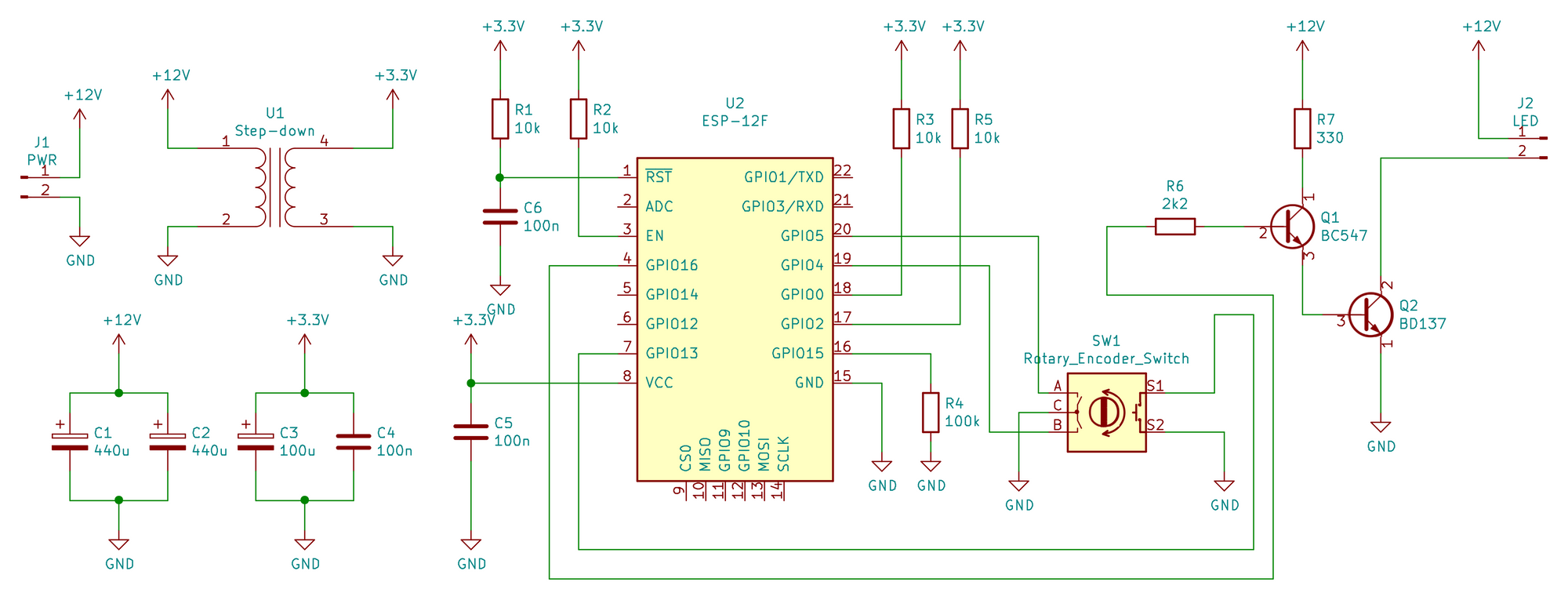
[Schematic notes: the transformer symbol for the Step-down (U1) is a placeholder. We are using a small stepdown board.]
Pitfall #1: Darlington voltage drop
At first, the design was using a canonical darlington configuration:

However, if you follow that diagram, you will end up with a \(V_{CE}\) of 0.8V, which is quite high. This voltage drop means that the LED bars will be having only 11.2V –which doesn't seem a lot less than 12V, but it results in a noticeable light drop given the general personality of LEDs.
At this point you have several options:
- Keep it like that
- Increase the supply voltage to 12.8V
- Change the Darlington topology
We chose the third option and got a \(V_{CE}\) close to 0.1V, which results in an inappreciable lighting difference.
Pitfall #2: Capacitors, capacitors, capacitors
Having a wall power supply results in a long 12V cable between the circuit and the power supply, plus the fact that vendors tend to make those power supplies small by skimping on capacitors. Also, because we are dimming the lights through a PWM, there will be current spikes.
Remember to include some reasonably beefy capacitors for the 12V line. Some capacitance at 3.3V will also be advisable (you don't want the ESP to reset due to a voltage drop when there are current spikes!). And always include a ceramic 100nF small capacitor close to your digital chips –i.e. the ESP– for high-frequency filtering and general stability.
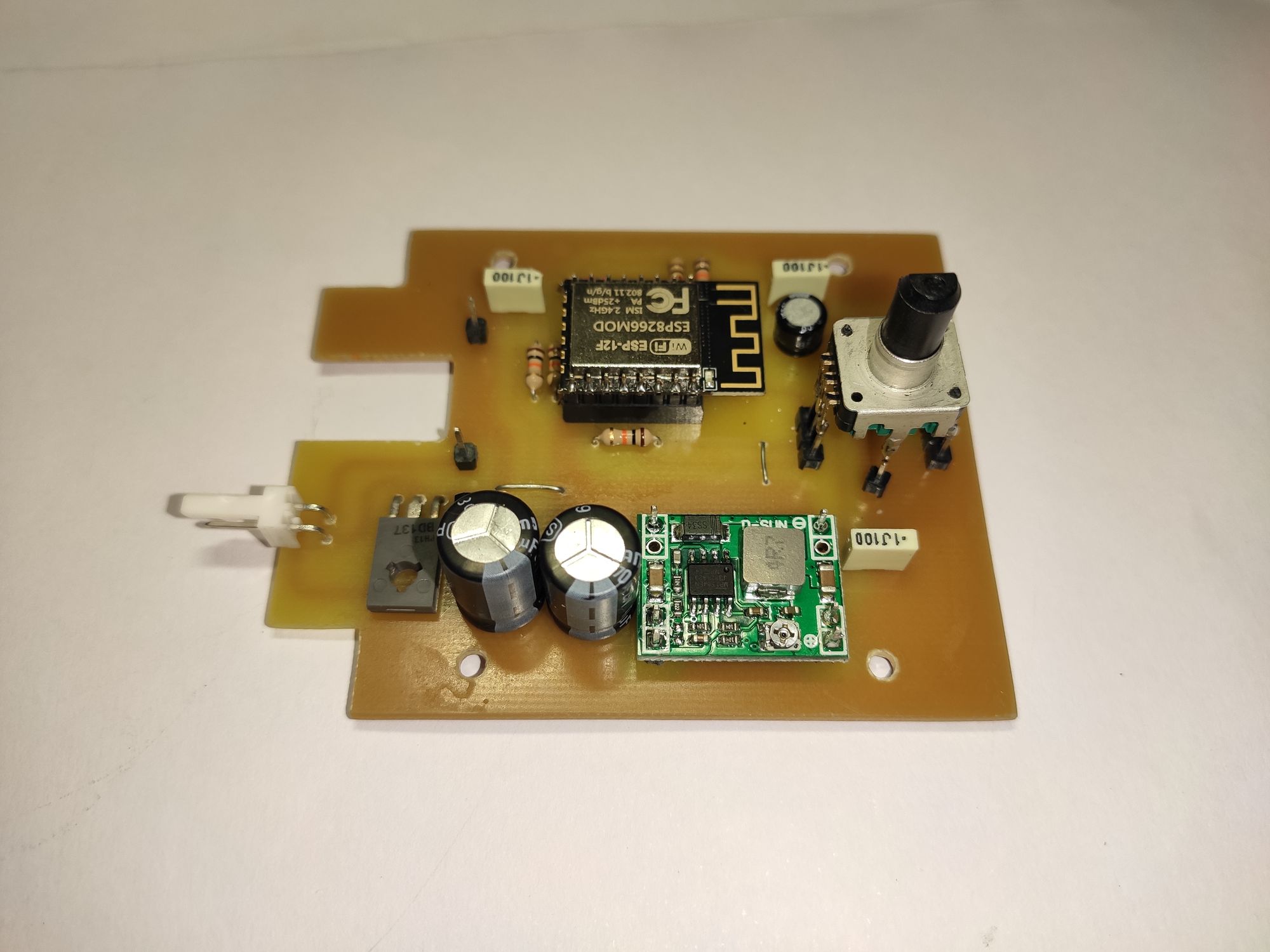
The build
The software
We are using ESPHome because we are used to it and it integrates nicely into our home automation ecosystem --i.e. Home Assistant. The relevant part of the configuration is the following:
binary_sensor:
  - platform: gpio
    id: "encoder_button"
    pin:
      number: GPIO13
      mode: INPUT_PULLUP
      inverted: true
    on_click:
      then:
        - light.toggle: piano_overhead

sensor:
  - platform: rotary_encoder
    id: encoder
    pin_a:
      number: GPIO5
      mode: INPUT_PULLUP
      inverted: true
    pin_b:
      number: GPIO4
      mode: INPUT_PULLUP
      inverted: true
    min_value: 0
    max_value: 60
    on_value:
      then:
        - light.turn_on:
            id: piano_overhead
            transition_length: 0s
            brightness: !lambda |-
              // range 0 - 1.0
              return id(encoder).state / 60.0;

light:
  - platform: monochromatic
    name: "Piano overhead"
    id: "piano_overhead"
    output: pwm_output

output:
  - platform: esp8266_pwm
    id: pwm_output
    pin: GPIO16
It may seem intimidating at first –if you are not used to those configuration files– but it is quite straightforward and you can easily tweak it to your use case.
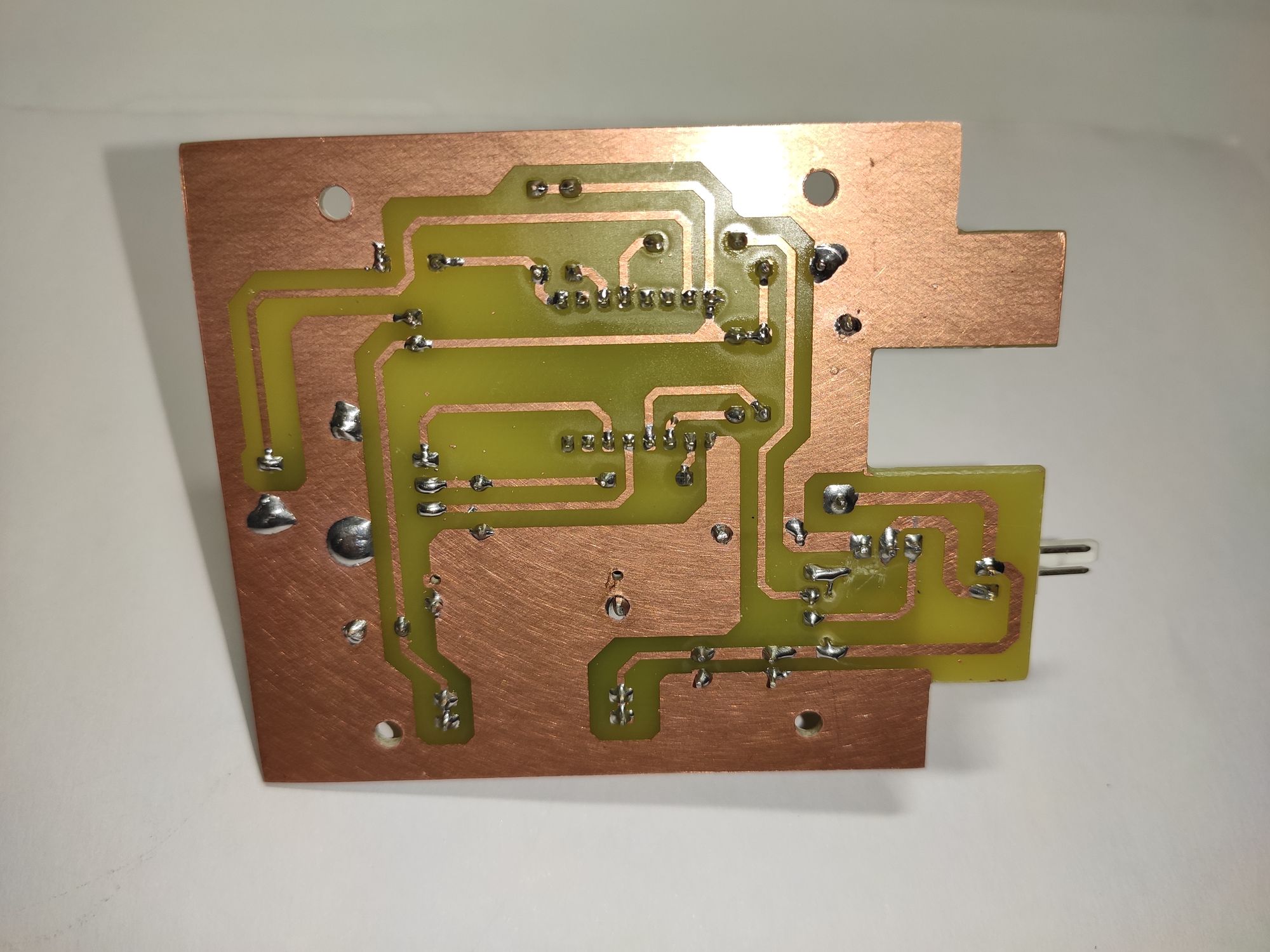
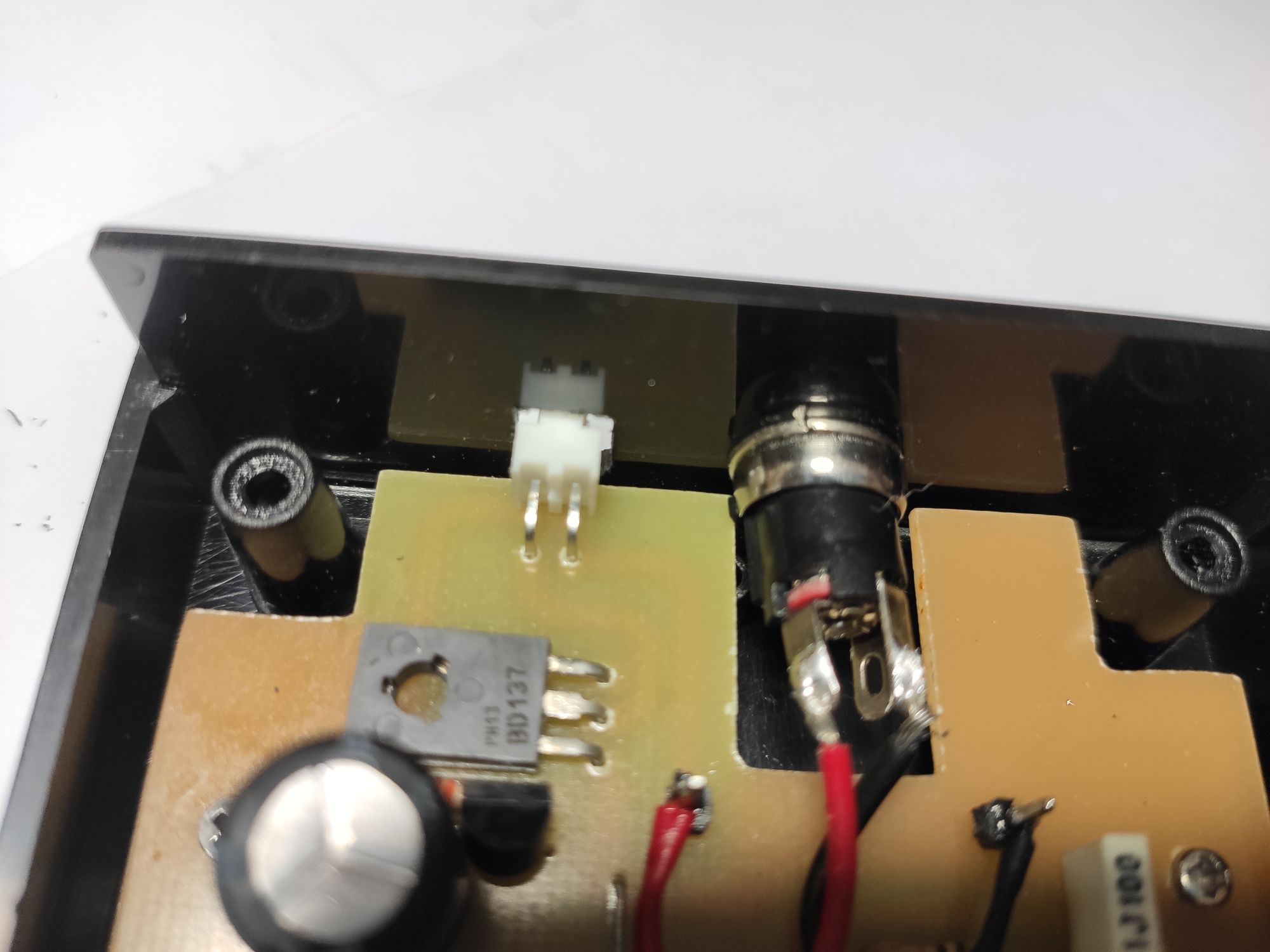
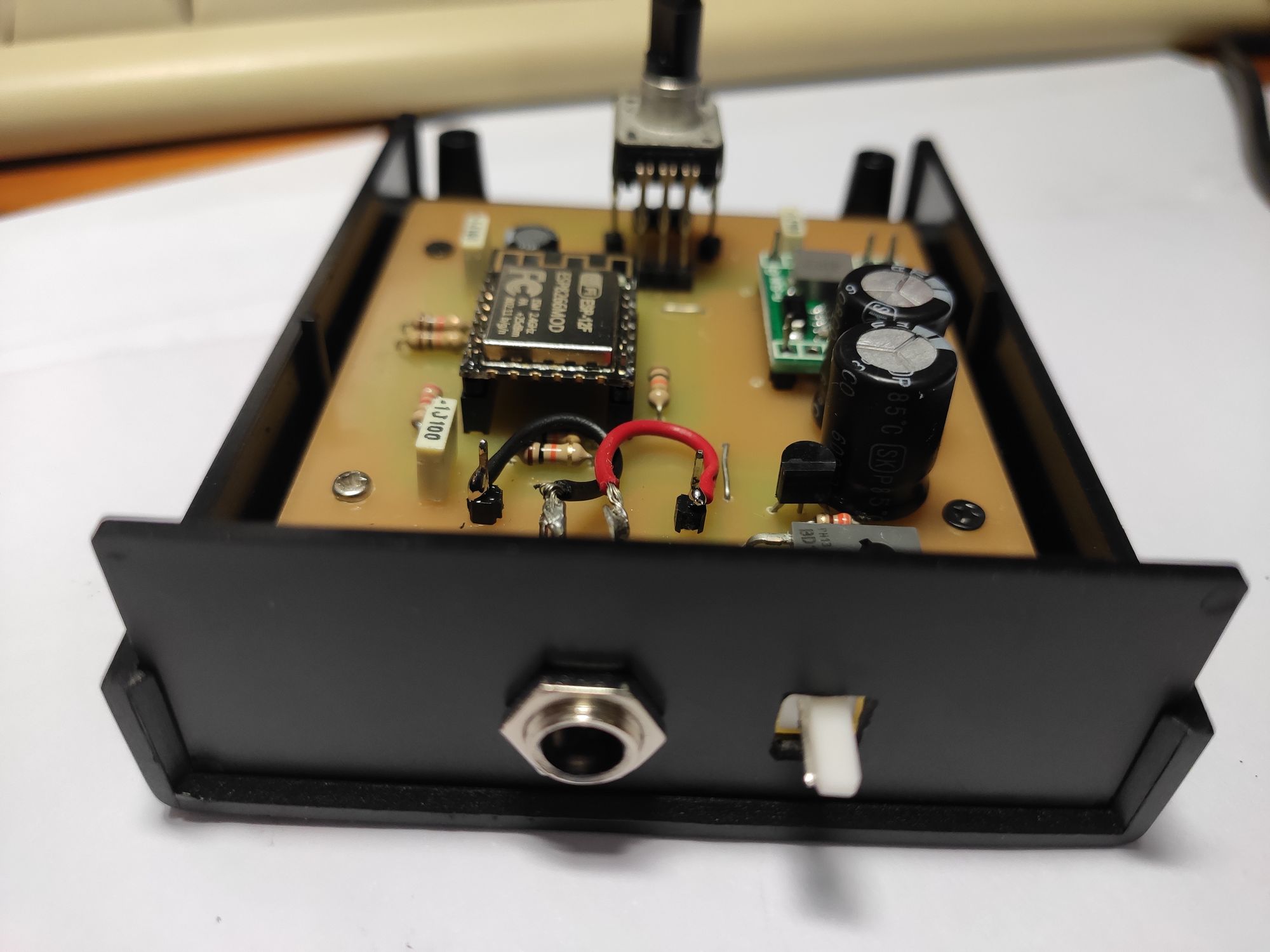
PCB & box
Simple box, simple connections: a barrel connector for the 12V input and a KK 254 series for the light. The first is chassis mounted and the latter is soldered to the PCB –soldering connectors to the PCB makes the placement of the PCB a little trickier, but in this case it was worth it. The rotary encoder has some creativity in order to heighten it a little bit.
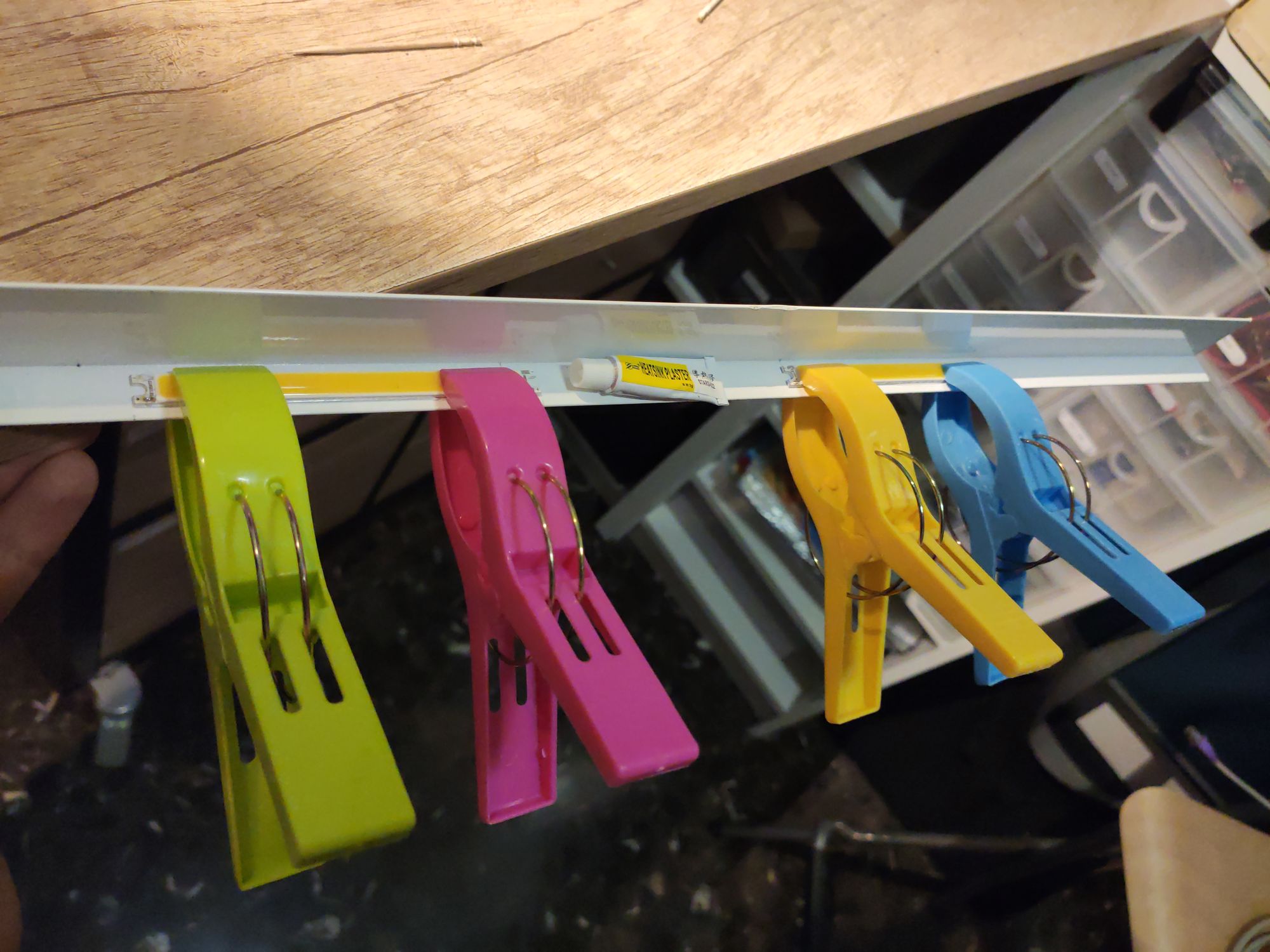
COB LED mounting
The COB strips can generate some heat and it is a good idea to mount them onto an aluminum profile. This simplifies installation and cabling and helps heat dissipation.
In this case, a simple heatsink plaster is enough to hold the lights in place. A photo of the process where you can see half of it:
Mounting it in place
Before mounting you should add the cables, obviously. Simply solder things and connectors and you are done. For this case we simply daisy-chained the COB LEDs (physical daisy-chain which is electric parallel connection) but if you have cheap devices and/or a lot of them, you may want to add addition voltage injection point to avoid voltage drop. You will realize you need that if after cabling everything the "last light" is noticeably less bright than the first one --which indicates a high voltage drop.
Finally, we just used double-sided tape and fixed that to the shelf where it should sit:
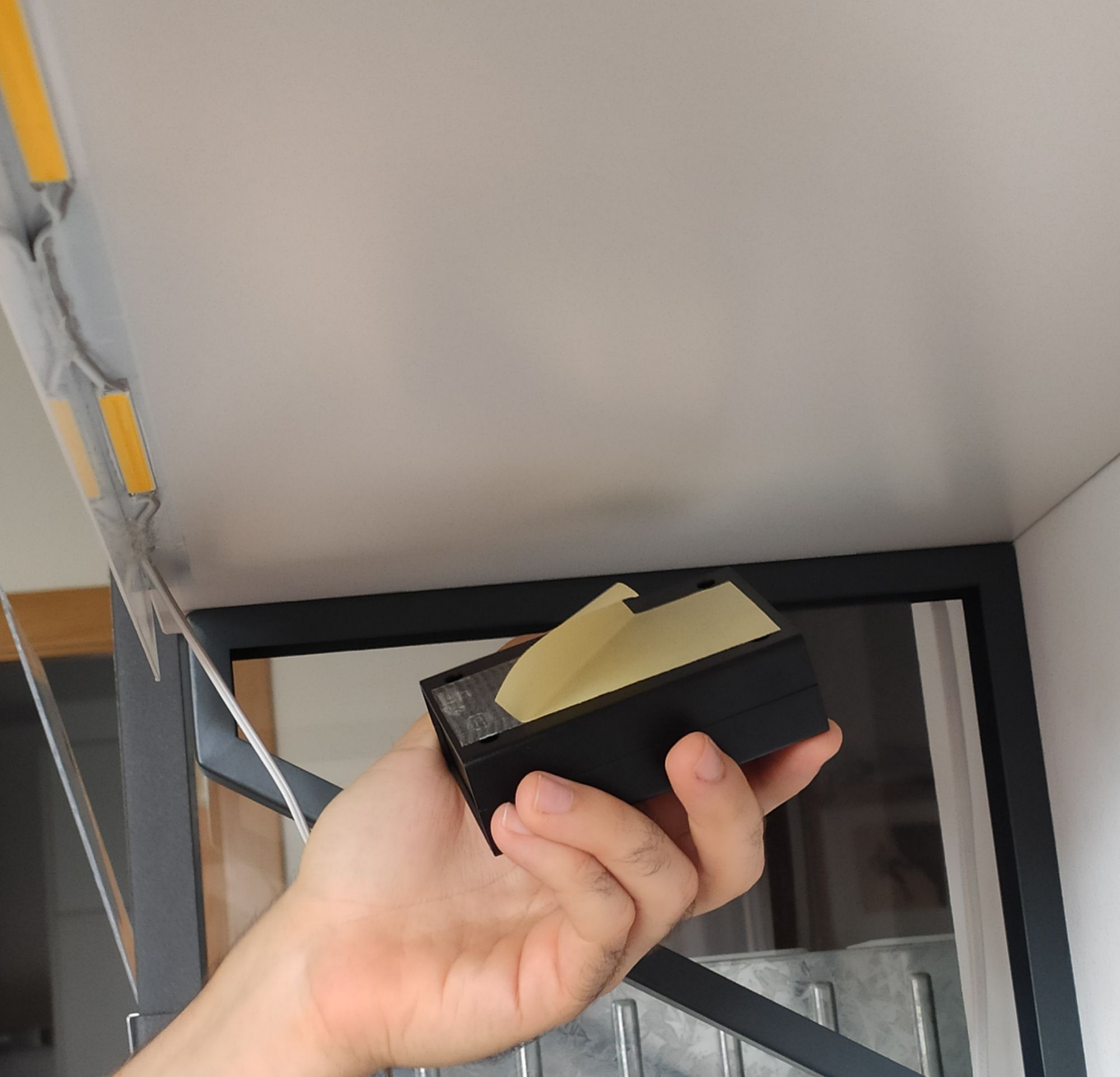
Pitfall #3: Don't let double-sided tape catch heat
We don't know if the double-sided tape is a good mid-term idea. Heat seems to have a great impact on them, and the lights may fall soon. We will jump to some construction adhesive or add some screws, we'll see.
If you want to fix this kind of lightning to an existing piece of furniture, think on how --maybe you don't want to drill holes, or you prefer some mechanical non-intrusive bracketing support, or whatever works for you. Just keep in mind that I do not recommend double-sided tape for things that can heat up.
Final result
I have to say, it is a very nice light to have on top of piano!
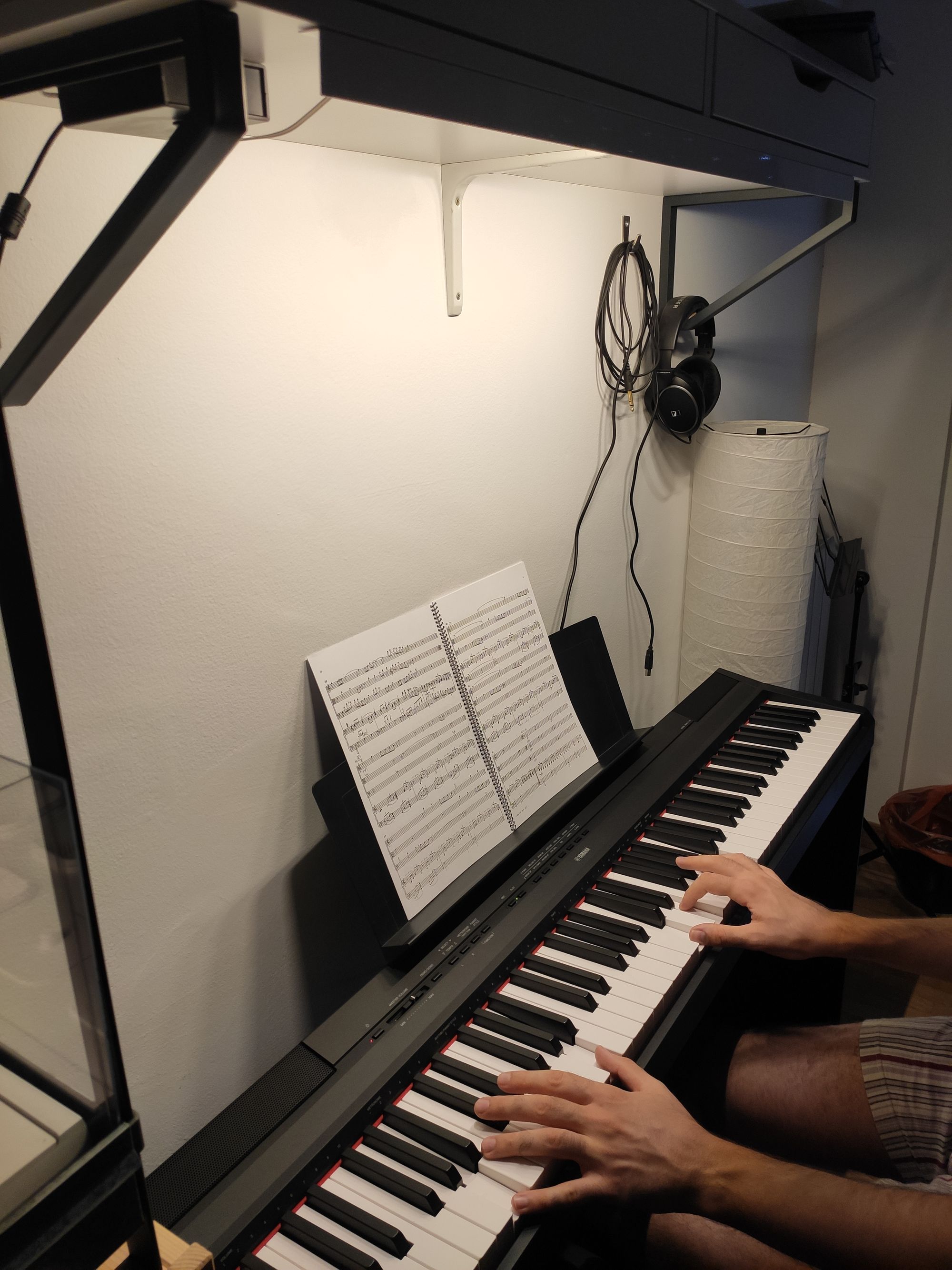
The warmth of the light is adequate for reading scores and playing piano. Having a rotary encoder easily accessible from the piano seat makes this light very convenient.
At the end, it works even better than what I envisioned.